SPCP355.300 Smart PSU
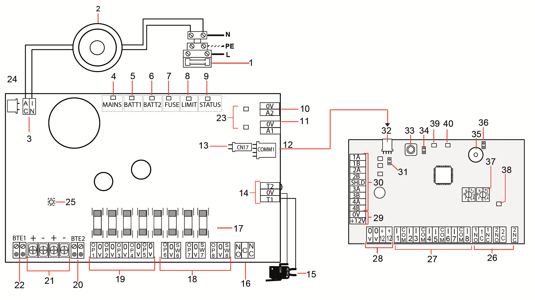
The SPCP355.300 Smart PSU is a power supply combined with an 8-input/2-output expander, contained in a G5 housing. The PSU is backed up by either 2x24Ah, or 2x27Ah batteries, and provides eight power and four logical outputs
The expander monitors the PSU for overcurrent, fuse failures, AC voltage, communications, and battery output. The expander is powered by, and receives data from, the PSU via a connector cable. It also interfaces with the SPC controller over the SPX X-BUS.
|
Number |
Description |
|---|---|
|
SPCP355.300 Smart PSU |
|
|
1 |
Mains input and fuse block |
|
2 |
Input transformer |
|
3 |
AC IN — AC power input |
|
4 |
MAINS — Mains power LED |
|
5 |
BATT1 — Battery 1 charge state LED |
|
6 |
BATT2 — Battery 2 charge state LED |
|
7 |
FUSE — Fuse fail LED |
|
8 |
LIMIT — Current limit LED |
|
9 |
STATUS — Status LED |
|
10 |
A2 — 14.5V power output.
|
|
11 |
A1 — Connects to the power input (+/-) on the SPC5350/6350. |
|
12 |
COMM1 — Expander 4-pin interface. Connects to item 32, power and data connection, in image above, with a straight-through cable. |
|
13 |
Clock Reference — Connects to Clock Reference on SPC5350/6350. |
|
14 |
T1, T2 — Tamper switch inputs. Connect these to the Front/Back tamper switch. |
|
15 |
Front back tamper switch. See Mounting the housing with tamper protection. |
|
16 |
NO/NC — Configurable NO/NC logical relay output. See Wiring the Outputs for more information. |
|
17 |
Glass fuses — 400mA T fuses for outputs 1-8. |
|
18 |
OP 6–8 and SW 6–8 — Combined power outputs (OP) and logical outputs (SW). Standard 12V DC power outputs combined with configurable, open-drain, logical outputs (4k7 EoL supervised/unsupervised). |
|
19 |
OP 1–5 — Standard 12V DC power outputs. See warning note below this table for more information. |
|
20 |
BTE2 — Battery 2 temperature monitoring input. |
|
21 |
BATT1 and BATT2 — Battery 1 and 2 connectors. |
|
22 |
BTE1 — Battery 1 temperature monitoring input. |
|
23 |
PTC fuses — Fuses rated at 300mA. Protecting the A1 and A2 outputs. For more information see System Recovery. |
|
24 |
PTC fuse — Fuse rated at 5A. Protects the AC power input (item 3 in image above). For more information see System Recovery. |
|
25 |
PSU Kickstart Switch — For more information see System Recovery. |
|
Expander |
|
|
26 |
NO/NC — Logical relay outputs. The expander provides two configurable NO/NC logical relay outputs. For more information, see Wiring the Inputs. |
|
27 |
I 1–8 — Inputs. The expander has 8 on-board inputs which can be configured as intruder alarm zones on the SPC system. For more information, see Wiring the Inputs. |
|
28 |
Auxiliary power supply 12V — Do not use. Expander is powered through COMM1 on the SPCP355.300 Smart PSU. |
|
29 |
X-BUS Input power — Do not use. Expander is powered through COMM1 on the SPCP355.300 Smart PSU. |
|
30 |
X-BUS Interface — The communications bus connects expanders on the SPC system. |
|
31 |
Termination Jumper — This jumper is always fitted, by default. For more information, see Wiring the X-BUS Interface. |
|
32 |
PSU 4-pin interface — Connects to COMM1 on the SPCP355.300 Smart PSU (item 12 in image above), power and data connector, with a straight-through cable. |
|
33 |
Front tamper switch — Not used. The Front/Back tamper connected to T1 and T2 of the SPCP355.300 Smart PSU is the only tamper required by this installation. |
|
34 |
JP1 — Front tamper bypass must be fitted. |
|
35 |
Buzzer — Activated to locate the expander. See Locate for more information. |
|
36 |
JP6 — Back tamper bypass. Must be fitted. |
|
37 |
Manual addressing switches — Enable manual setting of the ID of the expander. |
|
38 |
X-BUS Status LED — Indicates the X-BUS status, when the system is in Full Engineer mode, as follows:
|
|
39 |
LED — Not used. |
|
40 |
PSU Status LED. |
|
WARNING: The combined maximum load current drawn from all 12V DC outputs (OP 1–8) plus COMM1, should not exceed 2.4A. Each individual output, and output A2, should not exceed 300mA. If the device current requires more than 300mA, it is recommended to parallel the outputs. |
Adding extra expanders
If adding extra expanders to the G5 housing, you must ensure the front and back tampers are deactivated by fitting the appropriate jumpers. In a G5 housing, the front and back tamper is handled by the housing itself and the SPCP355.300 Smart PSU.