Mounting the housing with tamper protection
To mount the housing:
-
Using the supplied mounting template, mark the 4 drill positions for fixing the housing to the wall.
-
Drill and install suitable screws (see enclosed template) into the wall. Leave the screws protruding 1.5cm from the wall.
-
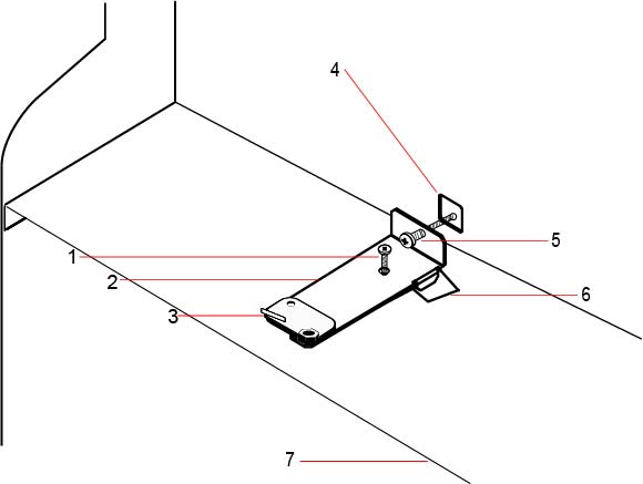
The G5 housing is pre-configured for front tamper only. To configure the housing for both front and back tamper, remove the front tamper securing screw (item 1).
The tamper bracket swings to the far right of the orientation slot (item 6).
-
Mount the G5 housing in the appropriate position on the wall and tighten the 4 mounting screws. Ensure that the housing is flush with the wall surface.
-
Move the tamper bracket to the far left of the orientation slot and tighten the back tamper screw (item 5) to the wall. The tamper bracket should be perpendicular to the back wall of the housing.
-
Install the lid on the housing to test the tamper switch connection. Lift the lid by approximately 1mm to activate the tamper switch.
|
Number |
Description |
Number |
Description |
|---|---|---|---|
|
1 |
Front tamper securing screw |
5 |
Back tamper screw |
|
2 |
Tamper bracket |
6 |
Orientation slot |
|
3 |
Tamper switch |
7 |
Shelf separating battery compartment |
|
4 |
Back tamper cutout |
|
WARNING: If the back tamper screw is not secure against the wall, then tamper protection is compromised. If the housing is removed from the wall or displaced, the back tamper contact needs to be tested again for proper functionality and re-adjusted if required. |