Controller Hardware 42xx/43xx/53xx/63xx
This section describes the controller for the SPC42xx, 43xx, 53 xx and 63xx models. The SPC5350 and 6350 are described in Controller Hardware SPC5350 and 6350.
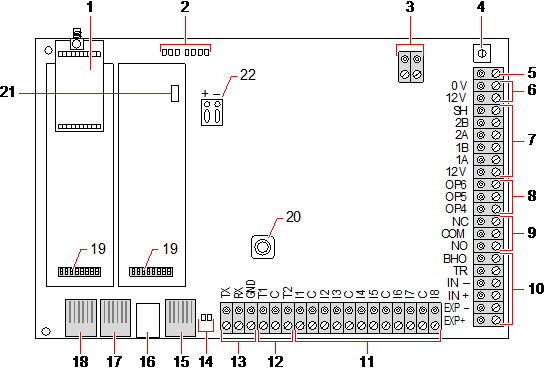
The SPC controller provides 8 on-board wired zones and optional wireless zones.
|
Number |
Name |
Description |
|---|---|---|
|
1 |
Optional wireless module |
The controller PCB can be factory fitted with a wireless module for use with wireless (868MHz) sensors. |
|
2 |
SPC status LEDs |
These 7 LEDs display the status of various system parameters as described in Controller status LEDs. |
|
3 |
AC power input |
A/C Mains Input: |
|
4 |
Reset button |
Warning: Defaulting the controller to factory settings deletes all configuration files, including backups, stored on the controller. All isolates and inhibits are also deleted. It is recommended you backup your configuration to a PC before defaulting the controller. Note: This feature is not available if engineer lockout is enabled. |
|
5 |
Earth connection terminal |
This terminal is not required and should not be connected. |
|
6 |
Auxiliary 12V output |
The SPC controller provides an auxiliary 12V DC output that can be used to supply power to expanders and devices such as latches, bells, etc. See Powering expanders from the auxiliary power terminals. The maximum deliverable current is 750mA. Note: The amount of current drawn is subject to the amount of time to be held up under battery conditions. |
|
7 |
X-BUS interface |
This is the SPC communications bus used to network expanders together on the system. See Wiring the X-BUS interface. SPC4000 only has 1 X-BUS interface. |
|
8 |
On-board outputs |
Outputs OP4, OP5, and OP6 are 12V open collector resistive outputs that share a 400mA current rating with the auxiliary 12V output. If the outputs are not connected to the 12V of the controller and are powered from an external power source the 0V of the power source needs to be connected to the controller 0V and the external power source cannot exceed 12V. |
|
9 |
Relay output |
The SPC controller provides a 1A, single-pole, changeover relay that can be used to drive the strobe output on the external bell. |
|
10 |
Internal bell/external bell |
Internal and external bell outputs (INT+, INT-, EXT+, EXT-) are resistive outputs with a 400mA current rating. The BHO (Bell Hold Off), TR (Tamper Return), and EXT outputs are used to connect an external bell to the controller. The INT+ and INT- terminals are used to connect to internal devices such as an internal sounder. See Wiring an internal sounder. |
|
11 |
Zone inputs |
The controller provides 8 on-board zone inputs that can be monitored using a variety of supervision configurations. These configurations can be programmed from system programming. The default configuration is Dual End of Line (DEOL) using resistor values of 4k7. See Wiring the zone inputs. |
|
12 |
Tamper terminals |
The controller provides 2 additional tamper input terminals that can be connected to auxiliary tamper devices to provide increased tamper protection. These terminals should be shorted when not in use. |
|
13 |
Serial port 2 terminal block
|
Serial port 2 terminal block (TX, RX, GND) may be used to interface to an external modem or PC terminal program. Serial port 2 shares a communications channel with the back-up modem. If a back-up modem is installed, ensure that no devices are connected to this serial port. |
|
14 |
Ethernet connectivity LEDs |
The 2 Ethernet LEDs indicate the status of the Ethernet connection. The left LED indicates data activity on the Ethernet port; the right LED indicates the Ethernet link is active. |
|
15 |
Ethernet interface |
The Ethernet interface provides for the connection of a PC to the controller for the purposes of programming the system. |
|
16 |
USB interface |
This USB interface is used to access browser programming or a terminal program. |
|
17 |
Serial port 2
|
This RS232 serial port may be used to interface to an external modem or PC terminal program. Serial port 2 shares a communications channel with the back-up modem. If a back-up modem is installed, ensure no devices are connected to this serial port. |
|
18 |
Serial port 1 |
This RS232 serial port may be used to interface to an X10 protocol device. |
|
19 |
Optional plug-in modules |
A primary (left slot) and back-up (right slot) module can be connected to the controller. These modules can be GSM or PSTN modems offering increased communication functionality. The back-up modem should not be connected if serial port 2 interface is connected to an external modem or other device. |
|
20 |
Front tamper |
This on-board front tamper (switch and switch) provides the housing tamper protection. Note: The front tamper is not used in the G5 housing. |
|
21 |
Battery selector |
J12: Fit jumper for 17Ah battery use and remove for 7Ah battery. Please Note: This selector is only available on 2.3 revision controller PCB. |
|
22 |
Auxiliary power input |
12V input from battery or PSU**. |


* Default setup for SPC5350 and SPC5360 panels
** PSU only applies to SPC5350 and SPC6350 panels.