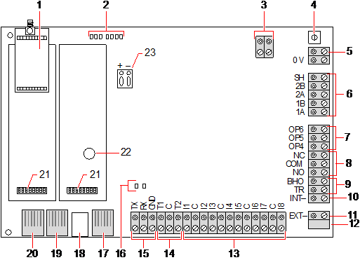
Controller Hardware SPC5350 and 6350
This section describes the SPC5350 and SPC6350.
|
The expander that is connected to the power supply within the G5 is set to ID1 by default. This setting should not be changed. |
|
Number |
Name |
Description |
|---|---|---|
|
1 |
Optional wireless module |
The controller PCB can be factory fitted with a wireless module for use with wireless (868MHz) sensors. |
|
2 |
SPC status LEDs |
These 7 LEDs display the status of various system parameters as described in Controller status LEDs. |
|
3 |
Clock Reference |
A clock reference signal can also be applied to this 2-pin connector to maintain accurate system time. Connect to Clock Reference CN17 on SPCP355.300 Smart PSU. |
|
4 |
Reset button |
Warning: Defaulting the controller to factory settings deletes all configuration files, including backups, stored on the controller. All isolates and inhibits are also deleted. It is recommended you backup your configuration to a PC before defaulting the controller. Note: This feature is not available if engineer lockout is enabled. |
|
5 |
Earth connection terminal |
This terminal is not required and should not be connected. |
|
6 |
X-BUS interface |
This is the SPC communications bus used to network expanders together on the system. See Wiring the X-BUS interface. Terminals 1B and 1A must be connected to SPCP355.300 I/O Expander terminals 2B and 2A, respectively Terminals 2A and 2B must be connected to terminals 2A and 2B, respectively, of the next expander on the X-BUS. |
|
7 |
On-board outputs |
Outputs OP4, OP5, and OP6 are 12V open collector resistive outputs with a 300mA current rating. The OP4 load must be connected to the SPCP355.300 Smart PSU. |
|
8 |
Relay output |
The SPC controller provides a 1A, single-pole, changeover relay that can be used to drive the strobe output on the external bell. |
|
9 |
Bell Hold-Off (BHO) and Tamper Return (TR) |
The BHO (Bell Hold Off) and TR (Tamper Return) (and EXT output) are used to connect an external bell to the controller. See Wiring an internal sounder. |
|
10 |
Internal Bell (negative) |
The INT- terminal is used to connect to internal devices such as an internal sounder. The power for the internal sounder must be connected to the SPCP355.300 Smart PSU. |
|
11 |
External Bell (negative) |
The Ext- terminal is used to connect to external devices such as an external bell. The power for the external sounder must be connected to the SPCP355.300 Smart PSU. |
|
12 |
Do not use. |
Do not use. |
|
13 |
Zone inputs |
The controller provides 8 on-board zone inputs that can be monitored using a variety of supervision configurations. These configurations can be programmed from system programming. The default configuration is Dual End of Line (DEOL) using resistor values of 4k7. See Wiring the zone inputs. |
|
14 |
Tamper terminals |
The controller provides 2 additional tamper input terminals that can be connected to auxiliary tamper devices to provide increased tamper protection. These terminals should be shorted when not in use. |
|
15 |
Serial port 2 terminal block |
Serial port 2 terminal block (TX, RX, GND) may be used to interface to an external modem or PC terminal program. Serial port 2 shares a communications channel with the back-up modem. If a back-up modem is installed, ensure that no devices are connected to this serial port. |
|
16 |
Ethernet connectivity LEDs |
The 2 Ethernet LEDs indicate the status of the Ethernet connection. The left LED indicates data activity on the Ethernet port; the right LED indicates the Ethernet link is active. |
|
17 |
Ethernet interface |
The Ethernet interface provides for the connection of a PC to the controller for the purposes of programming the system. |
|
18 |
USB interface |
This USB interface is used to access browser programming or a terminal program. |
|
19 |
Serial port 2 |
This RS232 serial port may be used to interface to an external modem or PC terminal program. Serial port 2 shares a communications channel with the back-up modem. If a back-up modem is installed, ensure no devices are connected to this serial port. |
|
20 |
Serial port 1 |
This RS232 serial port may be used to interface to an X10 protocol device. |
|
21 |
Optional plug-in modules |
A primary (left slot) and back-up (right slot) module can be connected to the controller. These modules can be GSM or PSTN modems offering increased communication functionality. The back-up modem should not be connected if serial port 2 interface is connected to an external modem or other device. |
|
22 |
Real-time clock battery |
Battery for real-time clock (RTC). |
|
23 |
Auxiliary power input |
12V input from A1 on SPCP355.300 Smart PSU. |
See also
Powering expanders from the auxiliary power terminals