Mounting a Back Tamper Kit
The SPC back tamper kit provides SPC control panels and power supplies with the option of having back tamper as well as front tamper.
The back tamper kit comprises the following parts:
-
Tamper switch
-
Leads for connecting the back tamper switch to the controller
-
Wall fixing plate
Mounting the Wall Fixing Plate
-
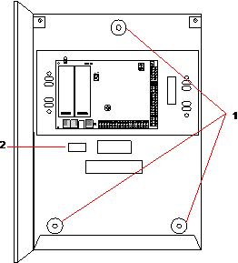
Mount the SPC in the appropriate position on the wall using all three fixings (see item 1 below).
-
Draw a line around the inside of the back tamper cut out (see item 2 above) to provide a guide for the wall plate on the fixing wall. Remove the housing from the wall.
-
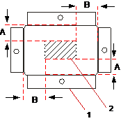
Place the wall plate (see item 1 below) on the wall centering it precisely around the rectangle previously drawn (see item 2 below).
-
Ensure all four flanges on the wall plate are flush with the wall.
-
Mark the four fixings on the wall plate.
-
Drill and use suitable screws (max. 4mm) for the wall substrate.
-
Fit the wall plate to the wall.
Fitting the Back Tamper Switch
-
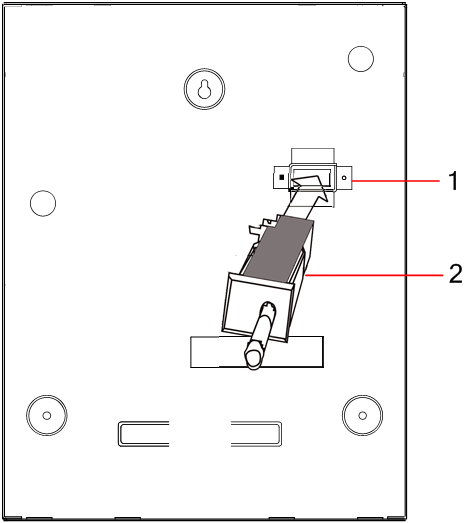
Insert the tamper switch (see item 2 below) into the back of the housing so that the plunger faces outwards (see item 1 below).
-
Fit the housing back onto the wall using the three fixings previously removed (see item 2 below). Visually check to ensure there is a flush finish between the wall plate and the housing metalwork.
Number
Description
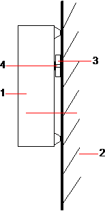
1
Housing
2
Wall
3
Wall Fixing Plate
4
Tamper Switch
|
WARNING: If the wall fixing plate is not accurately aligned then the housing will not sit properly on its fixings. |
Wiring the Back Tamper Switch to the Control Panel
All control panels have spare inputs configured as tamper inputs that are designed for wiring the tamper switch and do not require any programming.
This tamper switch will be referred to as ‘Aux Tamper 1’ by the system.
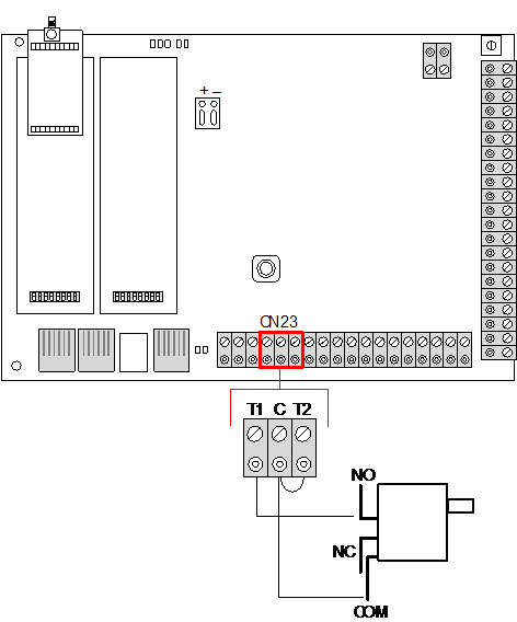
-
Connect NO on the tamper switch to T1 on the controller.
-
Connect COM on the tamper switch to C on the controller. Ensure the T2 jumper is not removed.
-
When the tamper switch is wired, the controller can be commissioned in the normal manner.