Expanders
-
Select Configuration > Hardware > X-Bus > Expanders.
For naming and identifying:
In loop configuration, each expander is numbered consecutively from the first (expander connected to the 1A 1B on the controller) to the last (expander connected to the 2A 2B on the controller).
Example for SPC63xx: Expanders, when numbered 1 through 63, are allocated zones (in groupings of 8) in subsequent identities of 1 to 512 (the greatest number in zone identification is 512). Therefore, any expander named or identified by a number greater than 63 has no allocated zones.
-
Click one of the expander identifying parameters to display the Expander Configuration page.
-
Configure the following fields:
Description
For appearance on device LEDs.
Volume Limit
Audio Expander Only: Speaker volume for the Audio Expander and satellites (WAC 11). They are all wired in parallel. Note that the speaker on WAC 11 has a potentiometer for fine-tuning the volume. Range is 0 min – 7 max or disabled.
Auxillary Channnel
Audio Expander Only: This option should be enabled if satellites (WAC11) are connected to this expander.
Note: This option, if enabled, powers the satellite microphones. The satellite speakers are always enabled regardless of this setting.
End Of Line
Select the correct End of Line (default: DEOL 4K7). This setting should match the actual wiring of the input on the controller or expander. See Wiring the system.
(Zone) Description
Provide a description for allocated zone.
(Zone) Type
Select the zone type. See Zone attributes.
Area
Select the area.
Attributes
Assign attributes as desired. See Zone types.
Outputs/PSU outputs (Displayed for the SPCP355.300 Smart PSU ONLY)
Output
The numbered output. The value in parentheses corresponds to the physical output on the PSU board.
Description
Provide description for output.
Change type
Change the type of output as necessary.
Attributes
Assign attributes to the output.
Test
Test the output.
Output monitor
Select which outputs are to be monitored.
Note: The parallel resistor, diode and required load must be applied before enabling this option. The SPCP355.300 must perform a calibration before monitoring starts. See Supervised Outputs for more information.
Primary battery only
Tick this box if there is no secondary battery connected to the PSU
When expanders are added or removed go to Configuration > Hardware > X-BUS > Cable Map & Configuration.
Click Reconfigure to implement changes.
|
When you click Proceed Reconfiguration, the whole X-BUS is reconfigured. If an expander is offline and the reconfigure button is pressed, the expander will disappear without notifying the user. |
Reconfiguring the X-BUS
-
Select Configuration > Hardware > X-BUS > Cable Map & Configuration.
-
Click Reconfigure.
The X-Bus cable Map – Warning(s) page displays.
-
Click Proceed Reconfiguration.
The X-BUS is reconfigured.
If an expander is offline and the reconfigure button is pressed, the expander will disappear without notifying the user.
See also
Configuring an Indicator Expander
There are 2 possible configuration modes for the indication expander:
-
Linked Mode
-
Flexible Mode
-
Select Configuration > Hardware > X-Bus > Expanders.
-
Click one of the indicator identifying parameters.
The following page is displayed for Linked Mode configuration.
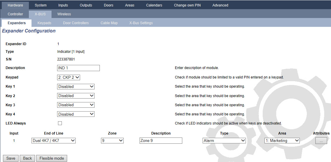
Linked Mode
-
Enter a description.
-
Select if indicator module should be limited to a valid code entered on a keypad.
-
Select the areas that are to be controlled by the 4 functions keys.
-
Configure the input.
Flexible Mode
-
Click the Flexible Mode button.
-
Configure the fields described in the table below.
Function Keys
Area
Select the area is to be controlled by the function key.
Function
Select the function to be performed by this key in this area.
Area
Select an area if the indicator module is located in a secure area.
Visual Indication
Indicator
There are 8 indicators/LEDs on the right and 8 indicators/LEDs on the left side.
Function
The function that is indicated by this LED.
Function On
Select the colour and the state for every indicator if the selected function is ON.
Function Off
Select the colour and the state for every indicator if the selected function is OFF.
Change function
Click this button to change the function for this indicator. The function can be enabled or used for a system, area, zone or keyswitch.
Audible Indications
Alarms
Select if the alarms should be audible.
Entry/Exit
Select if entry/exit should be audible.
Key press
Select if keypress should be audible.
Deactivation
Calendar
Select if indicator expander should be limited by calendar.
Mapping gate
Select if indicator module should be limited by a mapping gate.
Keyswitch
Select if indication module should be limited by a keyswitch.
Keypad
Select if indicator module should be limited to a valid PIN entered on a keypad. (see warning above)
Card reader
Select if indicator module should not be activated until a valid card/fob is presented to the built-in card reader.
-
Configure the input.
|
WARNING: Your system will not comply with EN standards if you enable a function key to set the system without a valid PIN being required. |
Configuring a Keyswitch Expander
-
Select Settings > X-Bus > Expanders.
-
Click one of the keyswitch identifying parameters.
-
Configure the fields described in the tables below.
Description
Enter a description for the keyswitch expander.
Key Options
Latch
Select if key position should be latched.
Latch timer
Enter duration of latch in seconds (0–9999, 0 means latch lasts until key is turned the other way).
Areas
Location
Select the area where the keyswitch is located.
Visual Indications
Indicator/LED
There is 1 indicator/LED on the right and 1 indicator/LED on the left side.
Function
The function for this indicator/LED.
Function On
Select the colour and the state for every indicator if the selected function is ON.
Function Off
Select the colour and the state for every indicator if the selected function is OFF.
Change function
Click this button to change the function for this indicator. The function can be enabled or used for a system, area, zone or keyswitch.
Deactivation
Calendar
Select if the keyswitch module should be limited by calendar.
Mapping gate
Select if the keyswitch module should be limited by a mapping gate.
Output
Output x
Configure and text the outputs for the keyswitch. See Editing an output for more details.
Keyswitch Functions
Centre, Right and Left Positions
Select the Function that that this keyswitch position will perform and the relevant Area.
Keyswitch functions are:
-
None
-
Unset
-
Partset A
-
Partset B
-
Fullset
-
Toggle Unset / Fullset
-
Toggle Unset / Partset A
-
Toggle Unset / Partset B
-
All Okay
-
Setting authorisation
-
Shunt
-
|
WARNING: Your system will not comply with EN standards if you enable a keyswitch function to set the system without a valid PIN being required. |