The SPC back tamper kit provides SPC control panels and power supplies with the option of having back tamper as well as front tamper.
The back tamper kit comprises the following parts:
Mounting the Wall Fixing Plate
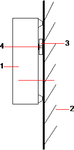
Mount the SPC in the appropriate position on the wall using all three fixings (see item 1 below).
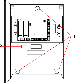
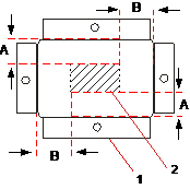
Place the wall plate (see item 1 below) on the wall centering it precisely around the rectangle previously drawn (see item 2 below).
Fitting the Back Tamper Switch
Insert the tamper switch (see item 2 below) into the back of the housing so that the plunger faces outwards (see item 1 below).
Fit the housing back onto the wall using the three fixings previously removed (see item 2 below). Visually check to ensure there is a flush finish between the wall plate and the housing metalwork.
| Number | Description |
|---|---|
|
1 |
Housing |
|
2 |
Wall |
|
3 |
Wall Fixing Plate |
|
4 |
Tamper Switch |
| WARNING: If the wall fixing plate is not accurately aligned then the housing will not sit properly on its fixings. |
Wiring the Back Tamper Switch to the Control Panel
All control panels have spare inputs configured as tamper inputs that are designed for wiring the tamper switch and do not require any programming.
This tamper switch will be referred to as ‘Aux Tamper 1’ by the system.