The LCD keypad is a wall-mounted interface that allows:
The LCD keypad unit includes an integral front tamper switch and has a 2 line x 16 character display. It features an easy-to-use navigation key to assist in locating required programming options, and has 2 context sensitive soft keys (left and right) for selecting the required menu or program setting. 3 LEDs on the keypad provide an indication of AC power, system alerts, and communications status.
The LCD keypad may be factory fitted with a Portable ACE (PACE) proximity device reader (see Overview of keypad types).
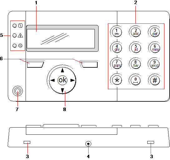
LCD keypad
| Number | Name | Description |
|---|---|---|
| 1 |
LCD display |
The keypad display (2 lines x 16 characters) shows all alert and warning messages and provides a visual interface for programming the system (engineer programming only). The display can be adjusted for contrast and under which conditions the backlight comes on. |
| 2 |
Alphanumeric keys |
Alphanumeric keypad allow for both text and numeric data entry during programming. Alphabetic characters are selected by applying the appropriate number of key presses. To switch between upper and lower case characters, press the hash (#) key. To enter a numeric digit, hold down the appropriate key for 2 seconds. |
| 3 |
Leverage access tabs |
The leverage access tabs provide access to the keypad back assembly clips. Users can unhinge these clips from the front assembly by inserting a 5mm screwdriver into the recesses and pushing gently. |
| 4 |
Back assembly securing screw |
This screw secures the front and back assemblies on the keypad. This screw must be removed to open the keypad. |
| 5 |
LED status indicators |
The LED status indicators provide information on the current status of the system as detailed in the table below. |
| 6 |
Soft function keys |
The left and right soft function keys are context sensitive keys to navigate through menus/programming. |
| 7 |
Proximity device receiver area |
If the keypad has been fitted with a proximity device receiver (see Overview of keypad types), users should present the Portable ACE Fob to within 1 cm of this area to SET/UNSET the system. |
| 8 |
Multi-functional navigation Key |
The multi-functional navigation key in combination with the keypad display provides an interface for programming the system. |
| LED | Status | |
|---|---|---|
|
AC mains (Green) |
|
Indicates the presence or failure of the mains supply FLASHING: AC mains fault detected STEADY: AC mains OK |
|
System alert (Yellow) |
|
Indicates a system alert FLASHING: System alert detected; display indicates the location and nature of alert. If the system is SET, then NO indication is given of system alerts OFF: No alert detected; If a keypad is assigned to more than one area, LED does not indicate an alert condition if any of those areas is SET |
|
X-BUS Status (Red) |
|
Indicates the status of the X-BUS communications when in FULL ENGINEER programming Flashes regularly: (once every 1.5 seconds approx) indicates communications status is OK Flashes quickly: (once every 0.25 seconds approx) indicates the keypad is the last expander on the X-BUS If the keypad is being installed for the first time and power is supplied to it before a connection to the controller X-BUS interface is made, the LED remains in the ON state |


